Transformer Vector Group Explained: A Buyer's Guide
Transformer Vector Group Explained: A Buyer's Guide
Understanding Transformer Vector Groups: A Practical Guide for International Buyers
When navigating the complex world of power transformers, especially for international projects adhering to standards like IEC 60076, KEPCO, or IEEE C57, you'll inevitably encounter the term "vector group." This seemingly arcane designation is, in fact, a critical specification that dictates how the windings of a transformer are connected and phased. For international buyers, a clear understanding of transformer vector groups is essential to ensure compatibility, safety, and optimal performance within their electrical grid. This guide will demystify transformer vector groups, providing a practical understanding for buyers worldwide.
What is a Transformer Vector Group?
At its core, a transformer vector group is a shorthand notation used to describe the configuration of the high-voltage (HV) and low-voltage (LV) windings and their relative phase displacement. It's a standardized way to communicate how the magnetic fields generated by the HV windings interact with those of the LV windings, and how the voltages produced at the terminals are phased with respect to each other. This configuration has significant implications for:
- Phase Relationships: It defines the angular displacement between the HV and LV voltages.
- Harmonics: Certain vector groups are better at mitigating or containing harmonic currents, which can be detrimental to power systems.
- Parallel Operation: It's crucial for ensuring transformers can be operated in parallel without causing circulating currents or voltage imbalances.
- Earthing/Grounding: The vector group influences how the neutral points of the windings are established and whether they are accessible for grounding.
Deconstructing the Vector Group Notation
The most common vector group notation, particularly under IEC standards, consists of a letter followed by a number. For three-phase transformers, it's typically expressed as a capital letter and a number, like 'Dyn11' or 'Yyn0'. Let's break down what these mean:
1. The High-Voltage (HV) Winding Connection (The Letter)
The first character (a capital letter) denotes the connection type of the high-voltage winding. The most common connections are:
- Y (or y): Star (Wye) Connection: In a star connection, one end of each winding is joined to a common neutral point. This is the most prevalent HV connection for large power transformers as it provides a neutral point that can be earthed, offering a path for fault currents and aiding in voltage regulation.
- D (or d): Delta Connection: In a delta connection, the windings are connected in a closed loop, forming a triangle. There is no inherent neutral point in a pure delta winding.
- Z (or z): Zigzag Connection: This is a less common connection, often used for specific applications like grounding or system stabilization, where windings are connected in a zigzag manner.
2. The Low-Voltage (LV) Winding Connection (The Number)
The second part of the notation (a number) indicates the connection type of the low-voltage winding. Similar letters are used, but lowercase is common for LV windings when the notation specifies both HV and LV distinctly. However, when the vector group is presented simply as a letter and number (e.g., Dyn11), the number refers to the LV connection. The common lowercase letters are:
- y (or Y): Star (Wye) Connection: As described above, with a neutral point.
- d (or D): Delta Connection: Closed loop, no inherent neutral.
- z (or Z): Zigzag Connection:
3. The Phase Displacement (The Number After the Letters)
This is arguably the most critical part for practical application. The number following the connection letters indicates the phase shift (in multiples of 30 degrees) between the line voltage of the HV winding and the line voltage of the LV winding. The numbering starts from 0, representing a 0-degree shift (in phase), and increases sequentially, with each increment representing a 30-degree lag of the LV voltage relative to the HV voltage.
- 0: 0-degree shift (in phase). The LV voltage is aligned with the HV voltage.
- 1: 30-degree lag.
- 2: 60-degree lag.
- 3: 90-degree lag.
- 4: 120-degree lag.
- 5: 150-degree lag.
- 6: 180-degree lag.
- 7: 210-degree lag (or 150-degree lead).
- 8: 240-degree lag (or 120-degree lead).
- 9: 270-degree lag (or 90-degree lead).
- 10: 300-degree lag (or 60-degree lead).
- 11: 330-degree lag (or 30-degree lead).
The most common phase displacement numbers encountered are 0, 1, and 11. For instance, 'Dyn11' means a Delta-connected HV winding, a Star-connected LV winding, with the LV voltage lagging the HV voltage by 330 degrees (or leading by 30 degrees).
Common Transformer Vector Groups and Their Applications
Let's look at some common vector groups and why they are chosen:
- Dyn11: (Delta-HV, Star-LV, 30-degree lead/330-degree lag) This is perhaps the most widely used vector group for distribution transformers. The delta HV winding helps to absorb or suppress third harmonics. The star LV winding provides an accessible neutral for grounding, which is crucial for safety and for connecting single-phase loads. The 30-degree phase shift is often compatible with grid requirements.
- Yyn0: (Star-HV, Star-LV, 0-degree shift) In this configuration, both HV and LV windings are star-connected, and they are in phase. It's often used for:
- Generators: To step up the voltage from generators.
- Interconnecting systems with the same phase relationship.
- When a neutral point is required on both sides.
- The neutral points are usually brought out and available for grounding.
- Dzn11: (Delta-HV, Zigzag-LV, 30-degree lead/330-degree lag) The zigzag LV winding is particularly effective at suppressing zero-sequence currents and can also help with harmonic mitigation.
- Dd0: (Delta-HV, Delta-LV, 0-degree shift) Less common for general power distribution due to the lack of an accessible neutral. Sometimes used for specific industrial loads or interconnecting delta systems.
- Yy0: (Star-HV, Star-LV, 0-degree shift) Similar to Yyn0, but the neutral might not be brought out or intended for grounding.
Why Vector Group Matters for International Buyers
As an international buyer, specifying the correct vector group is paramount for several reasons:
- System Compatibility: Ensuring the new transformer integrates seamlessly with existing grid infrastructure. Incorrect phasing can lead to circulating currents, voltage imbalances, and potential damage to connected equipment.
- Parallel Operation: If transformers are to operate in parallel (a common practice for redundancy and load management), they must have the same vector group, or at least compatible vector groups that can be easily synchronized.
- Harmonic Mitigation: Different vector groups have different characteristics regarding harmonic currents. Choosing the right group can help manage harmonic distortion, which is vital for maintaining power quality and equipment longevity.
- Earthing and Safety: The vector group dictates the availability of a neutral point for grounding. Proper earthing is a fundamental safety requirement and is often mandated by local grid codes (e.g., KEPCO standards).
- Load Type: The nature of the connected load can influence the choice of vector group. For example, the presence of sensitive electronic equipment might necessitate a vector group that minimizes harmonics.
- Standard Compliance: Adhering to international standards like IEC 60076, or national standards like those from KEPCO or IEEE, means understanding and specifying vector groups according to their requirements.
How to Specify the Correct Vector Group
When procuring transformers, international buyers should:
- Consult Grid Codes: Understand the specific requirements of the local utility or grid operator. For example, KEPCO (Korea Electric Power Corporation) has its own standards and preferred configurations.
- Review Existing Installations: If replacing or augmenting existing transformers, identify the vector groups of the current units to ensure compatibility.
- Work with Manufacturers: Engage with reputable transformer manufacturers. They have the expertise to recommend the appropriate vector group based on your application, system voltage, load characteristics, and applicable standards (IEC 60076, IEEE C57, etc.).
- Understand Harmonic Requirements: Discuss harmonic mitigation strategies with your manufacturer, as the vector group plays a significant role here.
- Consider Future Needs: Think about potential future expansions or changes in load patterns when making your selection.
Conclusion
The transformer vector group is more than just a technical detail; it's a fundamental characteristic that defines a transformer's operational behavior within a power system. For international buyers, a thorough grasp of this concept, alongside an understanding of relevant standards like IEC 60076 and IEEE C57, is crucial for making informed purchasing decisions. By carefully considering the connection types, phase displacement, and application requirements, you can ensure that the power transformers you procure from global suppliers like Korean manufacturers are safe, efficient, and perfectly integrated into your electrical infrastructure.
Recommended Products
Discover related products from our store
Read Next
Continue reading related articles curated for you.
Power vs. Distribution Transformers: Key Differences Explained
Explore the critical differences between power and distribution transformers, their roles in the electrical grid, key specifications, and governing standards like IEC 60076.
Read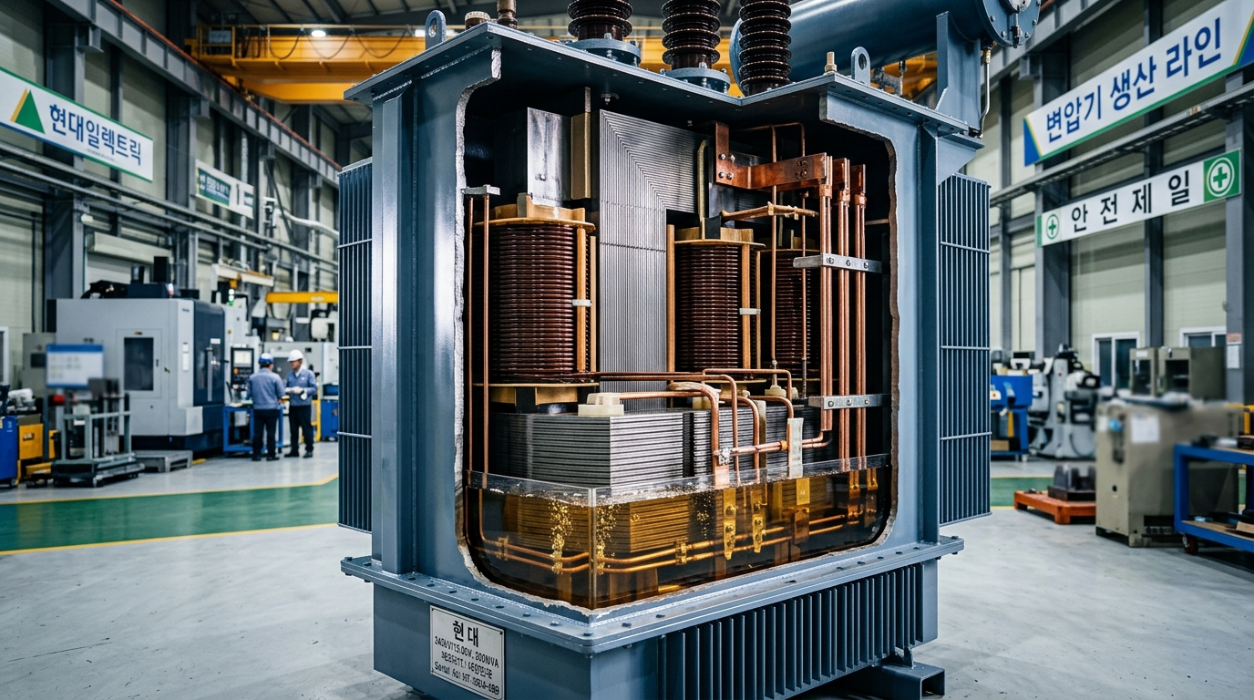
Inside a Transformer: Key Components & How They Work Together
Explore the critical components inside a power transformer, from the core to cooling systems, and discover how they synergize to ensure reliable, efficient power delivery. Learn about adherence to IEC 60076 and IEEE C57 standards for global markets.
Read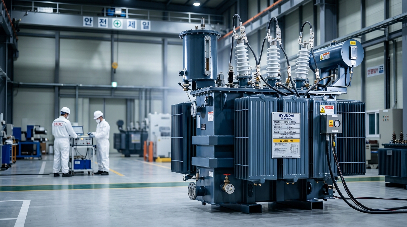
What Is a Transformer? Your Essential Guide to Powering the World
Demystify transformers with our simple guide for B2B professionals. Learn what a transformer is, how it works, its key components, and vital role in global power grids, adhering to IEC 60076 and IEEE C57 standards.
Read